- Computational Fluid Dynamics (CFD) has significant potential in the design, development, optimization, and performance improvement of Compressed Bio-Gas (CBG) plants. CFD can be applied to major equipment involved in biogas production, gas purification, compression, heat transfer, gas-liquid-solid mixing, and material handling.
- For CBG plants using agricultural biomass such as Napier grass, press mud, sugarcane waste, food waste, and other organic feedstocks, CFD can help improve plant efficiency, reduce energy consumption, optimize equipment dimensions, and minimize operational problems.
Major areas of CFD application in CBG plants
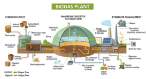
| Plant section | CFD application | Expected benefit |
|---|---|---|
| Biomass feeding | Screw conveyor, hopper and feeding system | Avoid blockages and improve feeding |
| Biomass preparation | Mixing, slurry preparation and dilution | Uniform slurry and reduced power |
| Anaerobic digester | Flow, mixing and dead-zone analysis | Better mixing and digestion |
| Agitator | Impeller design and optimization | Lower power consumption |
| Biogas collection | Gas flow and pressure distribution | Improved gas collection |
| H₂S removal | Gas-liquid contact and mass transfer | Improved H₂S removal |
| CO₂ removal | Scrubber and absorption column | Improved methane enrichment |
| VPSA system | Gas flow through adsorbent beds | Better flow distribution |
| Gas drying | Moisture separation and heat transfer | Improved gas quality |
| Gas compression | Compressor flow and thermal analysis | Improved compressor performance |
| Heat exchanger | Thermal and flow analysis | Improved heat recovery |
| Digestate handling | Slurry flow and pumping | Reduced pumping energy |
Detailed CFD applications
A. Anaerobic digester CFD analysis

The anaerobic digester is one of the most important areas for CFD application.
Objectives:
-
Analyze slurry flow patterns inside the digester.
-
Optimize agitator location, speed and impeller diameter.
-
Identify dead zones and stagnant regions.
-
Predict velocity and temperature distribution.
-
Evaluate solids suspension and sedimentation.
-
Analyze biogas bubble movement and gas-liquid interaction.
-
Optimize mixing energy consumption.
CFD models:
| Parameter | Recommended model |
|---|---|
| Flow | 3D Navier–Stokes |
| Turbulence | Realizable k-ε / SST k-ω |
| Multiphase | Eulerian / Mixture model |
| Gas-liquid interaction | Population balance, if required |
| Non-Newtonian slurry | Power-law / Herschel–Bulkley |
| Impeller rotation | MRF / Sliding Mesh |
| Heat transfer | Energy equation |
Important output parameters:
-
Velocity contours
-
Slurry circulation patterns
-
Dead-zone percentage
-
Mixing time
-
Power consumption
-
Temperature distribution
-
Solids concentration distribution
B. Agitator and mixing system optimization
CFD can be used to develop an optimized agitator for different digester geometries.
Parameters to investigate:
-
Impeller diameter.
-
Impeller blade angle.
-
Number of blades.
-
Rotational speed.
-
Agitator position.
-
Number of agitators.
-
Power number and torque.
Expected result: Identification of the optimum agitator configuration to achieve uniform mixing with minimum electrical power consumption.
C. Biogas scrubber – H₂S removal
CFD can support the design of H₂S removal equipment using chemical or biological scrubbing.
Analysis scope:
-
Gas and liquid flow distribution.
-
Pressure drop across packing.
-
Liquid distribution over packing.
-
Gas-liquid interfacial area.
-
H₂S absorption and mass transfer.
-
Identification of channeling and maldistribution.
Recommended models:
-
Multiphase Eulerian model.
-
Species transport.
-
Mass transfer model.
-
Chemical reaction model, where applicable.
D. CO₂ removal – Biogas upgrading scrubber
CO₂ removal is a critical process for achieving the required methane concentration in CBG.
CFD applications include:
-
Packed-bed absorber design.
-
Gas-liquid contact analysis.
-
CO₂ absorption and methane retention.
-
Liquid distribution optimization.
-
Pressure drop prediction.
-
Scrubber diameter and packing height optimization.
CFD can help compare water scrubbing, chemical absorption and other gas-upgrading configurations.
E. VPSA system – CO₂ separation
Vacuum Pressure Swing Adsorption (VPSA) is used for separating CO₂ from biogas.
CFD scope:
-
Gas distribution inside adsorption vessels.
-
Pressure and velocity distribution.
-
Flow uniformity through adsorbent beds.
-
Pressure drop across activated carbon or molecular sieve.
-
Adsorbent bed utilization.
-
Thermal effects during adsorption and regeneration.
-
Design of inlet and outlet distributors.
Recommended models:
-
Porous media model.
-
Species transport.
-
Adsorption isotherm and kinetic model.
-
Transient pressure and temperature analysis.
CFD can help minimize flow maldistribution and improve the effective utilization of adsorbent material.
F. Biomass feeding and slurry preparation
For plants using Napier grass, press mud, or agricultural waste, biomass handling and slurry preparation are important areas for CFD.
CFD analysis:
-
Biomass flow through screw conveyors.
-
Hopper flow and bridging analysis.
-
Slurry mixing and dilution.
-
Solid-liquid interaction.
-
Agitator performance in slurry preparation tanks.
-
Pump suction and discharge flow.
Expected benefits:
-
Reduced feeding problems.
-
Improved slurry homogeneity.
-
Reduced mechanical energy consumption.
-
Better equipment selection.
G. Heat exchanger and thermal system optimization
CFD can optimize heat exchangers used for maintaining digester temperature and recovering heat from process streams.
Applications:
-
Shell-and-tube heat exchanger analysis.
-
Slurry heating system.
-
Hot-water circulation.
-
Thermal stratification inside digesters.
-
Temperature uniformity.
-
Pressure drop and heat transfer coefficient prediction.
H. CBG compression and gas handling
CFD can be used for:
-
Compressor suction and discharge flow analysis.
-
Gas pipeline pressure drop.
-
Flow distribution in manifolds.
-
Pressure regulator and control valve analysis.
-
Gas cooling and heat transfer.
-
High-pressure filling manifold flow distribution.
For compressor internal aerodynamics, specialized rotating machinery CFD or vendor performance maps may be required.
3. CFD software and models for CBG plants
| Equipment | CFD model / approach | Suitable software |
|---|---|---|
| Digester | Multiphase, non-Newtonian flow | ANSYS Fluent |
| Agitator | MRF / Sliding Mesh | ANSYS Fluent, OpenFOAM |
| Slurry tank | Multiphase mixing | ANSYS Fluent |
| Screw conveyor | Moving mesh / DEM-CFD | Fluent, Rocky |
| H₂S scrubber | Species transport and mass transfer | ANSYS Fluent |
| CO₂ scrubber | Multiphase reactive absorption | ANSYS Fluent |
| VPSA | Porous media and transient species transport | ANSYS Fluent |
| Heat exchanger | Conjugate heat transfer | ANSYS Fluent |
| Gas pipeline | Compressible flow | ANSYS Fluent |
| Compressor | Rotating machinery | ANSYS CFX / Fluent |
4. Proposed CFD development projects for a CBG plant
The following projects can be developed as individual engineering studies or as part of a complete CBG plant design and optimization program.
| No. | CFD development project | Priority |
|---|---|---|
| 1 | Anaerobic digester mixing optimization |
High
|
| 2 | Digester agitator design optimization |
High
|
| 3 | Biomass slurry preparation tank |
High
|
| 4 | CO₂ removal scrubber optimization |
High
|
| 5 | H₂S removal scrubber optimization |
High
|
| 6 | VPSA gas distribution analysis | Medium |
| 7 | Slurry heat exchanger optimization | Medium |
| 8 | Biomass screw conveyor analysis | Medium |
| 9 | CBG compressor and piping analysis | Medium |
| 10 | Digestate handling and pumping system | Medium |
5. Proposed CFD methodology using ANSYS Fluent
A typical CFD project can follow this workflow:
CFD simulation workflow
-
Process data collection
Plant capacity, biomass properties, slurry flow rate, temperature, pressure, gas composition and equipment dimensions.
-
3D geometry development
Prepare digester, agitator, scrubber, heat exchanger or other equipment geometry in SpaceClaim.
-
Mesh generation
Generate a suitable computational mesh with local refinement around impellers, packing and complex flow regions.
-
Physics and model selection
Select turbulence, multiphase, species transport, porous media, chemical reaction and heat transfer models as required.
-
Boundary conditions
Specify mass flow, velocity, temperature, pressure, gas composition, rotational speed and material properties.
-
CFD simulation
Perform steady-state or transient simulations and monitor convergence and mass/energy balance.
-
Post-processing
Analyze velocity, pressure, temperature, species concentration, mixing time, torque and pressure drop.
-
Design optimization and validation
Compare design alternatives and validate against experimental or plant operating data.
6. Important process data required for CFD analysis
Before starting a CBG plant CFD project, the following information should be collected.
| Input parameter | Required information |
|---|---|
| Plant capacity | TPD of biomass or Nm³/day of CBG |
| Feedstock | Napier grass, press mud, food waste, etc. |
| Biomass properties | Density, moisture, particle size, solids content |
| Slurry properties | Density, viscosity, rheology |
| Digester | Diameter, height, working volume |
| Agitator | Type, diameter, RPM, motor power |
| Operating conditions | Temperature and pressure |
| Biogas composition | CH₄, CO₂, H₂S, water vapour |
| Scrubber | Diameter, height, packing type |
| VPSA | Vessel dimensions, adsorbent properties and operating cycle |
| Heat exchanger | Flow rates, inlet temperatures and outlet requirements |
7. Limitations and important considerations
CFD should be integrated with process engineering rather than used as a replacement for process design.
-
Biological methane production requires biochemical reaction kinetics, substrate characterization and microbial growth models.
-
Digester CFD alone cannot reliably predict methane yield.
-
Anaerobic digestion kinetics can be coupled with CFD using models such as ADM1.
-
Gas-liquid mass transfer and chemical absorption require appropriate experimental data.
-
Biomass slurry rheology must be measured because its viscosity can change with solids concentration and shear rate.
-
CFD results should be validated using pilot-scale or operating plant measurements.
8. Business opportunities for CFD in CBG plant engineering
CFD can become an engineering service for CBG plant developers, EPC contractors and equipment manufacturers.
Potential commercial services include:
| Service | Deliverable |
|---|---|
| Digester design optimization | Optimized mixing arrangement |
| Agitator development | Impeller geometry and power requirement |
| Scrubber design | Packing height, diameter and pressure drop |
| VPSA optimization | Gas distribution and pressure drop |
| Heat exchanger design | Thermal performance and pressure drop |
| Pump and pipeline analysis | Hydraulic performance |
| Plant troubleshooting | Identification of flow-related operational problems |
| Plant capacity expansion | Equipment modification recommendations |
9. My recommendation: Five high-value CFD projects
For developing a specialized CFD engineering service for the Indian CBG industry, I would initially concentrate on these five projects:
1. Anaerobic digester optimization
Mixing efficiency, dead zones, solids suspension and agitator power.
2. CO₂ and H₂S scrubber optimization
Gas-liquid contact, mass transfer, pressure drop and gas distribution.
3. Biomass slurry preparation
Slurry uniformity, mixing time, agitator selection and power consumption.
4. VPSA system optimization
Adsorbent utilization, gas distribution and pressure drop.
5. Digester heating system
Heat exchanger design, thermal efficiency and temperature uniformity.
Overall conclusion: CFD can contribute to the development of more efficient CBG plants by improving equipment design, reducing mixing and pumping power, optimizing gas purification equipment, and resolving operational problems. The strongest initial opportunities are digester mixing, slurry preparation and gas-cleaning equipment.
For a Napier grass-based CBG plant, I would recommend starting with a combined biomass slurry preparation + anaerobic digester + agitator CFD study, followed by CO₂ scrubber optimization.
I can also develop a detailed CFD project proposal for a 5 TPD or 10 TPD Napier grass-based CBG plant, including equipment-wise simulation scope, input data, ANSYS Fluent models, deliverables and estimated engineering effort.
