
Scope CFD Modelling in Various Equipment of CBG (Bio-CNG) Plant
- Compressed Biogas (CBG), also known as Bio-CNG, is emerging as an important renewable energy source in India. Increasing demand for clean fuels, waste-to-energy solutions and sustainable agricultural practices has created significant opportunities for the development of CBG plants using agricultural residues, Napier grass, sugarcane waste, press mud, food waste and other organic feedstocks.
- A typical CBG plant consists of biomass preparation, slurry mixing, anaerobic digestion, biogas collection, hydrogen sulphide (H₂S) removal, carbon dioxide (CO₂) removal, gas drying, compression and CBG storage.
- The performance of these processes depends on several fluid-flow and transport phenomena, including:
- Solid-liquid mixing and biomass suspension
- Gas-liquid interaction and mass transfer
- Flow distribution inside scrubbers and digesters
- Pressure drop and hydraulic performance
- Temperature distribution and heat transfer
- Gas separation and distribution efficiency.
- Computational Fluid Dynamics (CFD) provides an engineering approach to investigate these phenomena and optimize the design of process equipment before manufacturing and installation. Using CFD software such as ANSYS Fluent and OpenFOAM, engineers can evaluate equipment performance, identify design limitations and develop optimized process configurations.
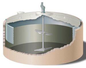
The following table provides an equipment-wise scope of Computational Fluid Dynamics (CFD) modelling for the design, development, performance evaluation and optimization of a CBG plant.
Equipment-wise CFD scope
| Sr. No. | CBG plant equipment | Scope of CFD modelling / analysis | Expected CFD outputs |
|---|---|---|---|
| 1 | Biomass Feeding Hopper | Biomass flow, particle movement, bridging, blockage and feeding uniformity | Particle distribution, velocity, flow pattern |
| 2 | Biomass Shredder / Crusher | Biomass particle movement, air flow, particle size reduction assessment and equipment flow optimization | Particle trajectories, velocity distribution |
| 3 | Slurry Preparation Tank | Solid-liquid mixing, agitator performance, slurry uniformity and dead-zone identification | Velocity contours, solid concentration, mixing uniformity |
| 4 | Biomass Digester (CSF/CSTR) | Slurry circulation, biomass suspension, gas-liquid-solid interaction, temperature distribution and dead-zone analysis | Velocity, temperature, gas holdup, solid distribution |
| 5 | Digester Agitator | Impeller design, blade angle, RPM, torque, power consumption and mixing efficiency | Torque, power, velocity vectors, mixing time |
| 6 | Digester Heating System | Heat transfer through heating coils, jackets or external heat exchangers | Temperature distribution, heat-transfer rate |
| 7 | Biogas Collection System | Gas flow distribution, pressure drop and gas collection efficiency | Pressure and velocity distribution |
| 8 | Gas-Liquid Separator | Gas-liquid separation, droplet entrainment and liquid carryover | Phase distribution, gas outlet quality |
| 9 | H₂S Scrubber | Gas-liquid interaction, H₂S absorption, liquid distribution and packed-bed pressure drop | H₂S concentration, pressure drop, mass transfer |
| 10 | CO₂ Scrubber | Gas-liquid contact, CO₂ absorption, packing performance and flow distribution | CO₂ concentration, absorption rate, pressure drop |
| 11 | PSA / VPSA System | Gas distribution, pressure variation, adsorbent bed flow and pressure drop | Pressure, velocity and species distribution |
| 12 | Membrane Separation System | Gas flow distribution, membrane-side pressure and species transport | CH₄/CO₂ concentration, permeate and retentate flow |
| 13 | Gas Dryer | Gas distribution, moisture separation and pressure drop | Velocity, pressure and moisture distribution |
| 14 | Biogas Blower / Compressor | Gas flow through impeller, pressure rise, velocity distribution and compressor performance | Pressure ratio, torque, power, efficiency |
| 15 | Slurry Transfer Pump | Impeller performance, slurry flow, pressure rise and cavitation | Pump head, torque, pressure, velocity |
| 16 | Gas Pipeline and Manifold | Gas distribution, pressure drop, flow maldistribution and local pressure losses | Pressure, velocity and flow distribution |
| 17 | Heat Exchanger | Fluid flow, heat transfer, temperature distribution and pressure drop | Heat duty, HTC, temperature contours |
| 18 | Biogas Flare | Gas-air mixing, combustion, flame stability and emissions | Flame temperature, heat release, CO and NOx |
| 19 | CBG Compression System | Gas flow, pressure and temperature distribution, compressor performance | Pressure rise, temperature, power consumption |
| 20 | CBG Storage Vessel | Gas filling, pressure and temperature distribution | Pressure and temperature variation |
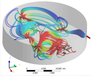
Detailed scope of major CFD applications
| Equipment | CFD simulation models | Important design parameters |
|---|---|---|
| Biomass digester | Multiphase flow, species transport, non-Newtonian flow, energy equation | Digester dimensions, slurry flow, solid concentration, viscosity |
| CSF/CSTR agitator | MRF, Sliding Mesh, turbulence, multiphase flow | Impeller diameter, RPM, blade angle, number of impellers |
| H₂S scrubber | Multiphase flow, species transport, porous media, mass transfer | Packing height, tower diameter, gas/liquid flow |
| CO₂ scrubber | Multiphase flow, species transport, chemical reaction, mass transfer | Solvent flow, packing type, temperature, pressure |
| Gas-liquid separator | VOF or Eulerian multiphase, turbulence | Vessel diameter, inlet velocity, outlet position |
| PSA/VPSA | Porous media, species transport, transient adsorption | Adsorbent properties, bed dimensions, pressure cycle |
| Slurry pump | Rotating reference frame, cavitation, multiphase | RPM, impeller geometry, flow rate, slurry properties |
| Heat exchanger | Conjugate heat transfer, turbulence | Flow rate, inlet temperature, tube geometry |
| Biogas flare | Species transport, combustion, radiation | Gas composition, gas flow rate, air supply |
Expected CFD project deliverables
| Sr. No. | Deliverable | Description |
|---|---|---|
| 1 | 3D CAD geometry | Equipment geometry preparation using ANSYS SpaceClaim |
| 2 | Computational mesh | Mesh generation and mesh quality evaluation |
| 3 | CFD setup | Material properties, physical models and boundary conditions |
| 4 | Flow analysis | Velocity vectors, streamlines and flow distribution |
| 5 | Pressure analysis | Static pressure and pressure drop |
| 6 | Thermal analysis | Temperature distribution and heat transfer |
| 7 | Multiphase analysis | Gas-liquid-solid distribution |
| 8 | Species analysis | CH₄, CO₂ and H₂S concentration distribution |
| 9 | Performance evaluation | Torque, power, mixing, pressure drop and mass transfer |
| 10 | Design optimization | Comparison of alternative equipment configurations |
| 11 | Technical report | CFD methodology, results, conclusions and recommendations |
Recommended priority for CFD projects in CBG plants
| Priority | Equipment | Main objective |
|---|---|---|
|
High
|
Biomass digester | Improve slurry circulation and mixing |
| High
|
CSF/CSTR agitator | Optimize impeller design and power consumption |
|
High
|
H₂S scrubber | Improve H₂S removal and gas-liquid contact |
|
High
|
CO₂ scrubber | Improve CO₂ absorption and methane recovery |
|
High
|
Slurry preparation tank | Improve biomass-water mixing |
| Medium | Gas-liquid separator | Improve separation efficiency |
| Medium | PSA/VPSA | Optimize gas distribution |
| Medium | Slurry pump | Improve hydraulic performance |
| Medium | Heat exchanger | Improve thermal performance |
| Medium | Biogas flare | Improve combustion performance |
Information required from CBG plant designer
| Sr. No. | Input data | Required information |
|---|---|---|
| 1 | Plant capacity | 1 TPD, 5 TPD, 10 TPD, etc. |
| 2 | Feedstock | Napier grass, press mud, agricultural waste, food waste |
| 3 | Process drawings | PFD, P&ID and equipment GA drawings |
| 4 | Equipment geometry | 3D CAD or manufacturing drawings |
| 5 | Process data | Mass flow rates, pressure and temperature |
| 6 | Fluid properties | Density, viscosity, thermal properties |
| 7 | Gas composition | CH₄, CO₂, H₂S and moisture |
| 8 | Agitator details | Impeller geometry, RPM and motor power |
| 9 | Scrubber details | Packing material, dimensions and liquid circulation |
| 10 | Operating data | Design and normal operating conditions |
- Recommendation: For an initial CBG plant CFD consultancy project, focus on three major areas: (1) biomass digester and CSF/CSTR agitator optimization, (2) H₂S scrubber design optimization, and (3) CO₂ scrubber performance optimization.
- These applications provide measurable engineering outputs for improving equipment design, mixing performance, gas quality and energy consumption.
- Note: CFD predictions of actual methane yield, biological conversion, H₂S/CO₂ removal and methane recovery require suitable biological/chemical models and validation against experimental or plant data.
Typical CBG Plant Process Flow
- The typical process sequence is:
Biomass receiving → Size reduction → Slurry preparation → Anaerobic digestion → Biogas collection → H₂S removal → CO₂ removal → Gas drying → Compression → CBG storage.
CFD modelling can support the design and optimization of individual equipment as well as the overall process integration.
CFD Modelling of H₂S Removal Systems
Importance of H₂S removal
Raw biogas generated from anaerobic digestion generally contains methane (CH₄), carbon dioxide (CO₂), hydrogen sulphide (H₂S), water vapour and trace impurities.
H₂S is a corrosive and toxic gas. Its presence can damage compressors, pipelines, engines and downstream gas-upgradation equipment. Therefore, H₂S removal is an essential step in CBG plant design.
Common H₂S removal technologies include:
-
Biological desulphurization.
-
Iron oxide-based adsorption.
-
Activated carbon adsorption.
-
Chemical scrubbing.
-
Wet scrubbing systems.
CFD modelling is particularly useful for optimizing gas distribution, liquid distribution, mixing and gas-liquid contact inside wet scrubbers and biological desulphurization systems.
Scope of CFD analysis for H₂S scrubbers
The main objective is to evaluate the gas and liquid flow distribution inside the scrubber and improve the contact between the two phases.
Major CFD simulation activities:
-
Development of 3D scrubber geometry, including inlet, outlet, packing and liquid distributor.
-
Gas velocity and pressure distribution inside the scrubber.
-
Liquid distribution over the packing material.
-
Gas-liquid interaction and interfacial area.
-
Identification of gas bypassing and liquid channeling.
-
Pressure drop across the packed bed.
-
H₂S concentration distribution along the scrubber height.
-
Evaluation of gas-liquid mass transfer and H₂S removal efficiency.
-
Optimization of packing height, diameter and liquid distributor arrangement.
CFD models and governing physics
The following models can be considered in ANSYS Fluent:
| CFD model | Application |
|---|---|
| Multiphase model | Gas-liquid interaction |
| Species transport | H₂S concentration distribution |
| Turbulence model (k-ε/k-ω SST) | Turbulent flow prediction |
| Porous media model | Packed-bed resistance |
| Mass transfer model | H₂S transfer between gas and liquid |
| Chemical reaction model | H₂S absorption or reaction, where applicable |
For a packed scrubber, the porous media approach can reduce computational requirements. However, it does not resolve individual packing geometry or directly predict liquid distribution around individual packing elements. A resolved packing model or calibrated two-phase packed-bed model may be required for detailed analysis.
Importance of CO₂ removal
Raw biogas typically contains approximately 50–65% methane and 35–50% CO₂, although actual composition varies with feedstock and operating conditions.
CO₂ reduces the calorific value of biogas. Its removal increases methane concentration and improves the quality of the upgraded gas.
Common CO₂ removal technologies include:
-
Water scrubbing.
-
Chemical absorption using amines.
-
Pressure Swing Adsorption (PSA).
-
Vacuum Pressure Swing Adsorption (VPSA).
-
Membrane separation.
CFD modelling can be applied to optimize the flow distribution and mass-transfer performance of CO₂ absorption columns, particularly water and chemical scrubbers.
Scope of CFD analysis for CO₂ scrubbers
The primary objective is to maximize gas-liquid contact and improve CO₂ absorption while minimizing pressure drop and pumping requirements.
Major simulation activities:
-
3D modelling of absorber and desorber columns.
-
Gas and liquid inlet distribution analysis.
-
Velocity distribution across the packed column.
-
Gas-liquid interaction and contact area.
-
CO₂ concentration distribution along column height.
-
Liquid circulation and distribution analysis.
-
Pressure drop across packing.
-
Mass transfer between gas and liquid phases.
-
Evaluation of CO₂ removal efficiency.
-
Optimization of packing configuration and column dimensions.
CFD models for CO₂ absorption
| Model | Purpose |
|---|---|
| Multiphase flow | Gas-liquid interaction |
| Species transport | CO₂ concentration prediction |
| Porous media | Packed column pressure drop |
| Mass transfer | CO₂ absorption |
| Chemical reaction | CO₂ reaction with solvent, where applicable |
| Energy equation | Temperature distribution and absorption heat |
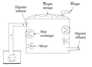
CFD Modelling of CSF Agitator in Biomass Digester
Importance of agitator design
The anaerobic digester is one of the most important components of a CBG plant. Organic biomass is mixed with water to prepare a slurry, which is fed into the digester for anaerobic digestion.
During digestion, microorganisms convert biodegradable organic matter into methane-rich biogas.
A Continuous Stirred Tank Reactor (CSTR), also described as a continuously stirred-flow digester, requires proper mixing to maintain uniform operating conditions.
An appropriately designed agitator helps:
-
Maintain uniform biomass slurry distribution.
-
Prevent sedimentation of heavy solid particles.
-
Reduce floating scum formation.
-
Improve microorganism-substrate contact.
-
Maintain uniform temperature.
-
Reduce stagnant zones.
-
Improve effective digester volume utilization.
Poor agitator design can result in dead zones, sludge accumulation, poor mixing and increased energy consumption.
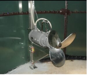
Scope of CFD analysis for CSF/CSTR agitators
The main objective is to optimize agitator geometry, impeller arrangement, rotational speed and power consumption.
Major CFD simulation activities:
-
Development of 3D digester geometry.
-
Modelling of impeller, shaft and baffles.
-
Definition of biomass slurry properties.
-
Simulation of agitator rotation using MRF or Sliding Mesh.
-
Velocity and flow circulation analysis.
-
Identification of dead zones and stagnant regions.
-
Solid particle suspension and sedimentation analysis.
-
Gas-liquid-solid multiphase flow analysis, where required.
-
Temperature distribution inside the digester.
-
Calculation of agitator torque and power consumption.
-
Optimization of impeller diameter, blade angle and rotational speed.
CFD models for agitator simulation
| CFD model | Application |
|---|---|
| Realizable k-ε | Turbulent flow in mixing tanks |
| k-ω SST | Turbulent flow and near-wall prediction |
| MRF | Steady-state rotating impeller analysis |
| Sliding Mesh | Transient impeller rotation |
| Non-Newtonian fluid model | Biomass slurry rheology |
| Eulerian multiphase | Gas-liquid-solid interaction |
| Discrete Phase Model | Particle trajectory analysis, where appropriate |
| Energy equation | Digester temperature distribution |
Important: Biomass slurry often exhibits non-Newtonian and shear-thinning behaviour. Therefore, experimentally determined rheological properties should be used rather than assuming water-like viscosity.
Important CFD parameters for agitator optimization
| Parameter | Engineering objective |
|---|---|
| Impeller diameter | Improve circulation |
| Impeller RPM | Optimize mixing intensity |
| Blade angle | Improve axial/radial flow |
| Number of impellers | Improve mixing throughout digester |
| Agitator torque | Calculate shaft loading |
| Power consumption | Reduce operating cost |
| Slurry velocity | Identify stagnant regions |
| Solid concentration | Evaluate suspension uniformity |
The following results can be generated using CFD:
-
Velocity magnitude contours.
-
Velocity vector plots.
-
Flow streamlines.
-
Slurry circulation patterns.
-
Solid volume fraction distribution.
-
Gas holdup and bubble distribution.
-
Temperature distribution.
-
Agitator torque and power consumption.
-
Mixing time and dead-zone identification.
Engineering benefit: CFD-based agitator optimization can help improve mixing uniformity, reduce sedimentation, minimize stagnant zones and reduce unnecessary agitator power consumption.
Comparative CFD Scope for CBG Plant Equipment
The following table summarizes the recommended CFD modelling approach for the three major equipment categories.
| Parameter | H₂S scrubber | CO₂ scrubber | CSF/CSTR digester |
|---|---|---|---|
| Main objective | H₂S removal | CO₂ removal | Biomass mixing |
| Flow type | Gas-liquid | Gas-liquid | Solid-liquid-gas |
| Primary model | Multiphase | Multiphase | Multiphase |
| Species transport | H₂S | CO₂ | Optional |
| Chemical reaction | As applicable | As applicable | Biological kinetics, if coupled |
| Porous media | Packing | Packing | Not normally required |
| Rotating zone | Not normally required | Not normally required | MRF/Sliding Mesh |
| Major output | H₂S removal | CO₂ removal | Mixing efficiency |
| Optimization | Packing and distributor | Packing and solvent flow | Impeller and RPM |
Input Data Required for CFD Modelling
For successful CFD analysis, the following design and process information should be collected from the CBG plant designer or equipment manufacturer.
| Equipment | Required input data |
|---|---|
| H₂S scrubber | Tower diameter, height, packing type, gas flow rate, liquid flow rate, inlet H₂S concentration, pressure and temperature |
| CO₂ scrubber | Column dimensions, packing details, gas composition, solvent properties, gas and liquid flow rates, pressure and temperature |
| Biomass digester | Digester diameter, height, operating volume, biomass feed rate, slurry concentration, density and viscosity |
| CSF agitator | Impeller diameter, blade geometry, number of impellers, RPM, shaft location and motor power |
| Biomass properties | Particle size, solid concentration, rheological properties and thermal properties |
| Operating conditions | Digester temperature, pressure, hydraulic retention time and slurry feed rate |
